")


")
")
")
Quick Break Test
Our company performs calibration of devices using the Quick Break system. The Quick Break Detector and Digital Oscilloscope are used for calibration.
“Quick break” or controlled interruption is a sudden stop (fast interruption) of the magnetizing current. This current interruption results in the transient (eddy) current induced in the component. The functionality of the quick break process can be defined as measuring how quickly the magnetic field induced by the coil is collapsed.
The quick break was discovered in the late 1950s, when it was found that when the DC current switched off, the field around the conductor quickly collapsed to zero. This fast energy change generates voltage and current that is in the opposite direction to the current in the circuit. This sudden breaking of a direct current at the end of the magnetization shot causes a transient current to be induced in the component. This resulting current increases considerably when quick break is applied to ferromagnetic material. This increase in the residual magnetic field within the component results in better field for inspection.
Original equipment for magnetic particle testing, which had the quick break function, disconnected the DC circuit in the coil and created an arc across the contacts. This ensured that the current dropped fast enough to zero to cause a transient current. This technique, however, caused significant wear on the contacts.
 In later models (Figure 1), researchers included silicon controlled rectifiers (SCRs), making it much easier to achieve quick break. Using a SCR switch-off time at zero transient current, along with the transformer secondary high voltage and open-circuit voltage, the researchers developed a controlled break. The controlled break is the main method used for controlled interruption in the magnetic particle testing equipment used today.
In magnetic particle testing (MT), the quick break technique is used to create a transient current within a component for detecting transverse discontinuities at the ends of the longitudinally magnetized bars. These types of discontinuities are often obscured by strong polarity at the ends of the bar. Using the quick break process, the resultant transient current ensures that the proper magnetic field remains at the ends of the bar, enabling the inspection for the transverse discontinuities.
 Figure 2 shows a rod that is longitudinally magnetized. Note the Figure 2a, which shows the bar without quick break, both ends become poles and the flux lines leave and enter the ends of the bar at an angle of 90° to the surface. Therefore, the near-end portions of the bar are not truly longitudinally magnetized, and any transverse indications in this area need not be reliably detected.
Figure 2b shows that when the same component is magnetized longitudinally and the current is quickly stopped by the quick break process, a transient current is generated that flows circularly inside the bar and generates a field near the surface, allowing the component to be truly longitudinally magnetized at the very ends of the bar. This makes it possible to detect transverse indications that are located at the very ends of the bar.
As with most techniques used in MT or any other non-destructive tests, there are standards or specifications that need to be followed. The first standards were military specifications, and since then they have been incorporated into the international ASTM specifications. Quick break method is no different. ASTM E 1444 and ASTM E 709 require that devices for magnetic particle testing with a quick break feature should be checked every six months (ASTM E 709-14, ASTM E 1444-12). ASTM standards require that only the fixed coil should be checked for quick break functionality. Headstocks would need to be checked only if cables are attached to the headstocks to form a coil wrap.
Another use of quick break magnetizing technique is when it comes to objects with structural changes that can produce a high internal magnetic flux density, resulting in an external polarity that can produce magnetic particle indications. Examples of such changes are inner grooves, wedge grooves or holes in the object. The problem with these types of irrelevant indications is that they can mask relevant indications. Quick break process can help to minimize, if not eliminate, indications from structural changes. Quick break process may advantageously be used in the case of ferrous metal products with high remanence. The magnetic field generated in these materials, when subjected to the quick break process, generates a very strong residual field. This strong residual field is advantageous if residual magnetization technique is to be used to perform MT. An example of applying this aspect is inspection of bearing rings.
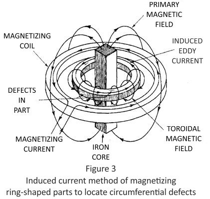
Another application of quick break is induced current magnetization. This method was developed for the magnetizing of ring-shaped parts such as bearing rings, without the need to make direct contact with the surface of the part. Figure 3 illustrates this effect. By making the ring a one-turn short circuited secondary of a “DC transformer”, a high current flowing circumferentially around the ring can be induced. For parts which have high retentivity, direct current with “quick break” can be used, and the parts are tested with the residual method. When the DC field is caused to collapse suddenly by the abrupt interruption of the magnetizing current, the circular field generated by the resulting transient current leaves the part with a strong residual field. The induction current method may benefit from the extremely strong quick break of the “contactor drop out” circuit. Finally, a few things should be kept in mind.
First, a quick break occurs only on a three-phase, full-wave rectified direct current device.
Second, devices are usually checked only on the coil circuit when the cables are attached to the headstocks to form a coil wrap. Furthermore, the quick break serves primarily to allow for the detection of transverse discontinuities at the ends of the part that has been longitudinally magnetized. And finally, the quick break is used as a feature of the current induction device.
Our company performs calibration of devices that use a quick break system.
The Quick Break Detector is used for calibration. (see photo)
The digital oscilloscope is also used for measurements.


